– Our Lifting Equipment Range


– Portable Lifting Jacks
Portable electric jacks for the rail transit/railroad industries are normally supplied as a set of four (4)lifting columns (or multiples as required) controlled by a Central Control Console. Each jack is equipped with a fixed or horizontally movable lifting cantilever. The columns are movable by hand or may be designed to be moved electrically on an embedded auxiliary rail.
- Practical & easy to move: This can be done by hand, with a forklift or even with a overhead crane.
- Control unit: Equiped with emergency stop & deadman push button for operation. Expandable units to add extra control panels.
- Pendant Controller: Provided on each jack for individual operation until lifting arm is in contact with load.
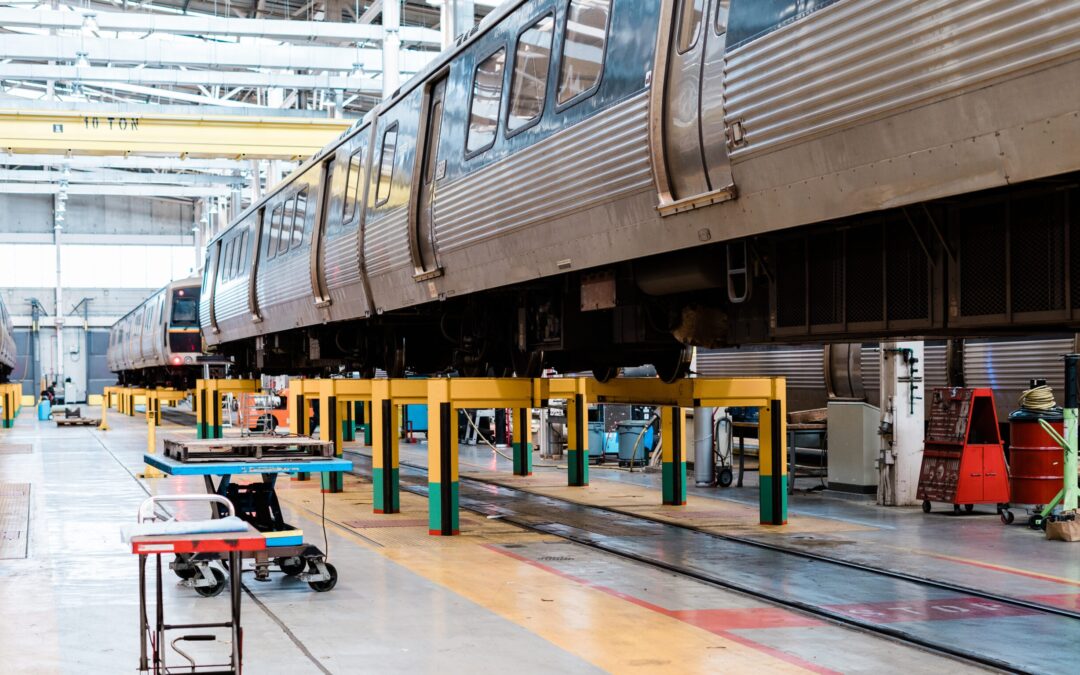
– Underfloor car truck hoist Body Stands
The car/truck hoist is designed for lifting bogies for maintenance, inspection, and repair work. The equipment usually consists of 4 car hoists, 8 body stands, and a complete electrical kit. Each hoist and stand comes with high and low limit switches, including emergency limit switches.
- Successive emergency limit switches and an automatic stop.
- Quality assurance: According to ISO 9000.
- Lifting power: 2 x 4.8 HP = 9.6 HP.


– Single Axle Drop Table
The drop table is used to release, lower, and transfer all single axle traction motors from any class 1 locomotive to and from a service track or multiple service tracks to a release area for replacement.
- Designed and fabricated to achieve smooth, quiet, convenient, and efficient operation.
- Numerous safety and self-monitoring features included.
- Full truck drop tables also available.
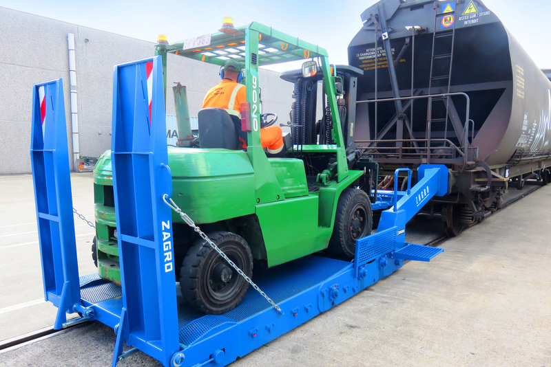
– Coupler Lift System 50-Ton
The lift is positioned by a forklift underneath the couplers of two railcars or under the body of a railcar with a high centersill. It is hydraulically operated with a remote control equipped hydraulic pump unit.
- Hydraulic pump unit with remote control
- Lifts fast, efficient, and safe
- A3-speed power shift with electronic controls


– Heavy Duty Mobile Support Stand
The support stand has a capacity of up to 15 tons with a cradle support pad. The stand is adjustable from 49 inches to 71 inches, in increments of four inches (4). The cradle support pad is fitted on a screw/nut irreversible device to allow the fine adjustment of the stand pad under the load.
- Other capacities available.
- Variable support heights possible via telescoping column design.
- Easy to move with 3 spring supported rolling wheels.
– Why choose our lifting equipment?

Exclusively supplied in North America
We represent the world’s premier manufacturers with superior engineering and quality standards. Our commitment is on advancing American railways operations with faster, safer and reliable equipment technology. See more about our approach and track record here

40 Years of Expertise
At Railquip we have built expertise on the design, supply, install and service & maintenance of Lifting Jacks & Lifting equipment across North America.

Safety Enhanced
Our tools are engineered to enhance the safety and reliability of your lifting tasks, ensuring that your operations run smoothly and securely. Including features like:
- Load sensors
- Nut wear detection
- Steel safety follower nut
- Automatic lubrication

Easier to Maintain
Our lifting equipment is designed to allow for enough height and space for maintenance procedures, this means you don’t need to take an extra effort by buying or creating self-made height extensions. Our lifts can save you money and reduce risks.

Durability & Extended Warranty
Our Portable jacks equipment’s standard lifetime goes up to 30 years. All jacks include a 2 year warranty.
Quality assurance: according to ISO 9000

Environmental Compliance
We offer a range of Portable Electric Jacks that not only optimize space but can contribute to achieve your sustainability goals with emission-free operation.
Request a call from north America’s Premier
Railroad Equipment Supplier
– Other Products